The most common issues arise when designs do not take into account the capabilities of the CNC machines and the geometry of the tooling used to fabricate the parts. We have listed the most common Design for Manufacturing (DFM) issues and how to avoid them. This is not intended to be an exhaustive list, but a general guideline to aid in the design process for machined components.
During three-axis milling (mill machining), the part is held or fixtured and the tooling is rotated. The cutting tools used for removing material are commonly available in standard diameters and lengths. If you are unfamiliar with the basic types of mill machining tooling (end mills, cutters, drills, reamers), an excellent and easy-to-use reference is the McMaster Carr website. Although McMaster Carr does not provide an exhaustive list of available tooling, it does offer a good overview of standard mill and lathe tooling. (www.mcmaster.com)
One of the most common DFM issues are parts designed with square inside corners, pockets, and holes. With standard tooling, it is impossible to produce a sharp inside corner perpendicular to the corner of the feature or pocket. As a general rule, the corner radius for an inside corner or pocket should not be less than 1/6 the depth of the pocket or height of the feature. For example, a pocket depth of .750 inches should not have a corner radius smaller than .125 inches.
As a general rule, pocket depths should be kept to 2 inches or less, depending on the pocket size and standard end mill length being used. Deeper pockets require specialized tooling and longer machining time to ensure a good surface finish, which increases cost.
Standard end mills can have a sharp corner, a corner break, a radius, or be spherical. When applying a full radius to all inside corners of a pocket, ensure that length of the standard spherical end mill meets the radius and depth requirements for the Square Holes/Pockets guideline. If your design has a different bottom radius or corner break, ensure the selected bottom radius or corner break is available in standard end mill tooling.
Your design should consider machining orientation to ensure that all features have adequate clearance and access for standard three-axis milling. The feature shown in the illustration has no access for machining.
As a general rule, your design should have wall thicknesses of .040 inches (1 mm) at a minimum. This thickness is necessary to provide sufficient rigidity for machining. The minimum wall thickness is greatly influenced by the part material, height and length of the wall.
It is best practice to use chamfers with standard chamfer tooling (90°, 82°, and 60°) rather than fillets for exterior features. Machining fillets require specialized fillet tooling or more complex 3D tool paths, which increases machining time and cost.
If your design requires an engraved logo or serial number, it is generally best to use recessed fonts versus raised ones, in order to decrease machining time and cost. Font size should be as large as allowable. Larger fonts allow larger tooling, decreasing machining time and reducing cost.
In general, the maximum depth of the whole should not exceed five times (5X) the diameter of the drill. This prevents the drill from wandering, and ensures adequate chip removal. Your design should use standard drill diameters whenever possible to decrease cost.
Drilled holes with standard tooling will leave a conical point at the bottom of the hole. Therefore, your design should include conical points at the bottom of drilled holes, or you should attach a drawing/image indicating that a drill point is acceptable at the bottom of the hole. If your design has a drilled hole up to a surface but does not penetrate, ensure there is adequate space to allow for the drill point.
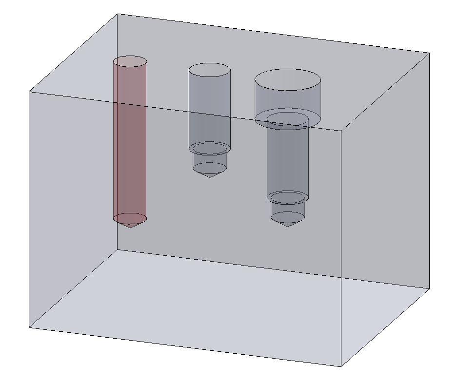
Standard taps have a limited threaded length and can only tap to a specific depth. Therefore, review your design to ensure that the depths of the tapped holes do not exceed the standard tap threaded length. A good rule of thumb is to keep the tapping depth at two times (2X) the diameter of the tap.
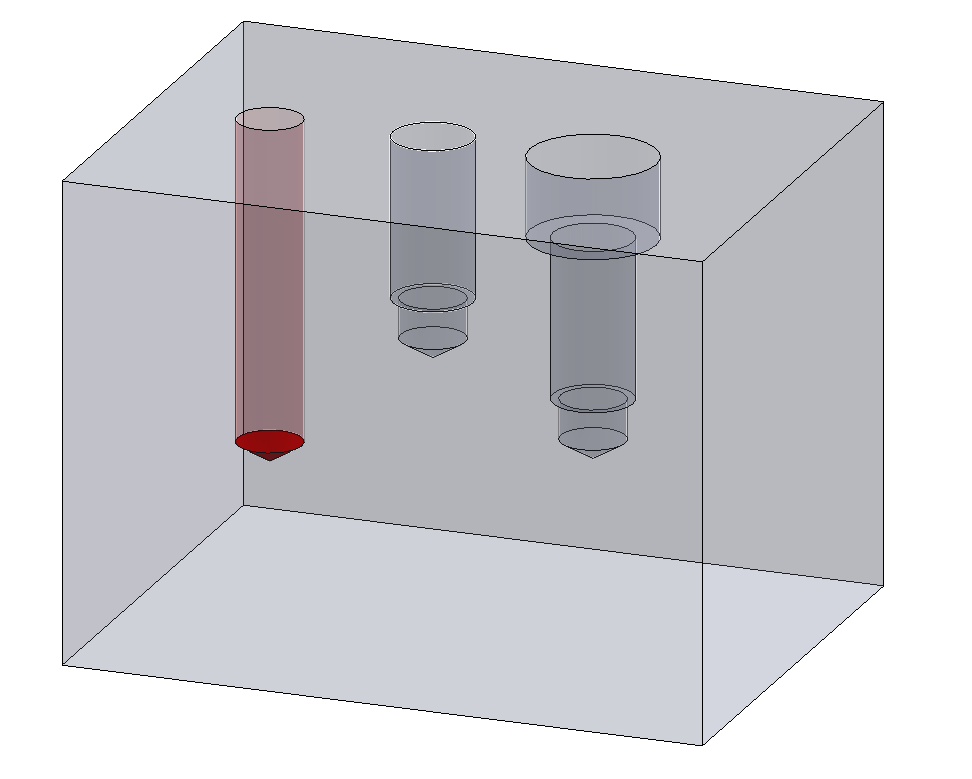
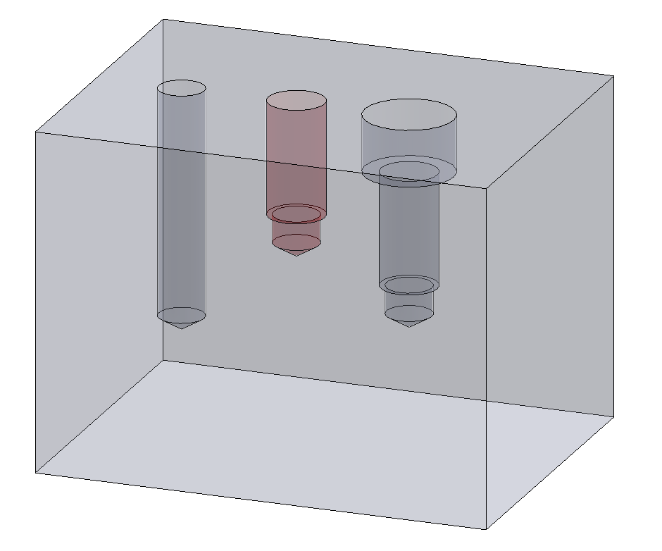
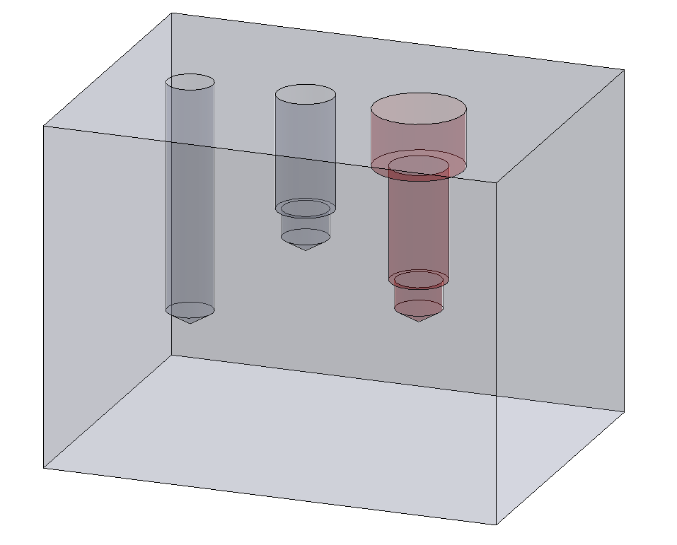
Blind tapped holes need a drilled hole depth greater than the thread depth. Typically, this extra depth needs to be three times (3X) the thread pitch to ensure adequate clearance for the tap at the bottom of the drilled hole. For example, a ¼-20 tapped hole with a thread depth of .5 inches would need a minimum drill hole depth of .650 inches.
If your design requires a deep tapped hole, you can add a counterbore, enabling the threaded portion of the tap to penetrate further into the hole. Designers often add extra thread depth in order to increase strength of a threaded connection. However, tests have shown only six threads of engagement are needed for full strength. A good rule-of-thumb for thread depth is two times (2X) the nominal thread diameter.
In 2-axis turning (lathe machining), the part is rotated, and the tooling is held and moved against the part. As in mill machining, McMaster Carr provides a good overview of the standard types of lathe tooling available (www.mcmaster.com)
In general, turned parts should be designed to be symmetrical around the rotational axis. In addition, if the turn parts need to be machined from both sides, consider how the part will be held for the second operation.
Generally, it’s best to design parts where the length-to-diameter ratio is less than five times (5X). Components made from plastic or softer materials will require even lower length-to-diameter ratios. Long, slender parts need additional support to prevent part deflection furthest from the lathe spindle. Using a tailstock can provide part support but will increase machining time and cost.
All lathe turning tooling will have some corner radius. Typically, the smallest radius is approximately .005 inches. Larger corner radii allow for larger, more robust tooling to be used, reducing machining time and cost. If your design does not include a corner radius, a minimum radius based on the appropriate lathe tooling will be added to your parts.
The same guidance as described in the milling (mill machining) section.
It is best practice to design/allow a thread relief at the end of an external thread on a turned part. Typically, the thread relief length will be two times (2X) the thread pitch at a minimum. For example, a ¼-20 external thread would have a minimum thread relief of .1 inches.
In general, the width and depth of the grooves should not exceed the limits of standard lathe tooling inserts. Internal grooves are also limited by the size of the tool holder required to access the internal groove location.